Due: ?
Reading: ...
In this lab, you will work with IPv6, configuring several devices to use the protocol in a manner analogous with several earlier labs that used IPv4.
We will use unique local IPv6 addresses (see RFC-4193) in this lab. These addresses are locally assigned and can be legitimately used without reference to a global authority. They serve the same role for IPv6 as the RFC-1918 addresses play for IPv4. Note: the "site-local" addresses described in the original IPv6 specifications are deprecated and should no longer be used.
All unique local IPv6 addresses have a prefix of FC00::/7. However, the least significant bit in the first octet of the address is set to 1 for locally assigned addresses. That is (currently) the only allowed setting of that bit; the value of 0 is reserved for future expansion. Thus, the prefix effectively becomes FD00::/8.
The next 40 bits are intended to be a locally generated random value. For this lab, we will use the prefix FD25:F376:7B60::/48. The next 16 bits of the address is the subnetwork number. The final 64 bits is the interface ID, as usual. In this lab, we will use 64-bit Extended Unique Identifiers (EUI-64) that can be automatically generated from an interface's MAC address.
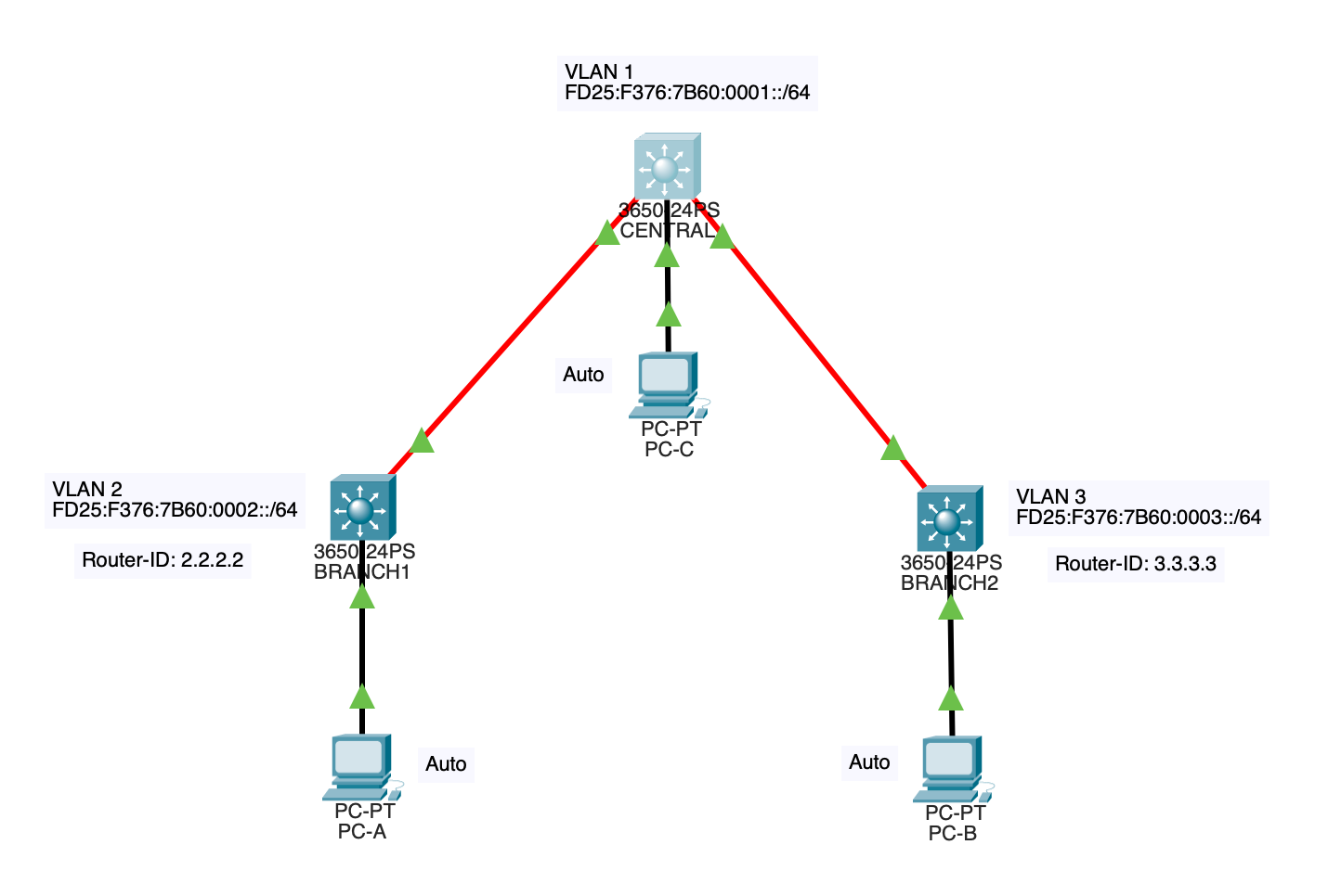
For this lab we will make use of the following topology:
The network is intended to simulate an organization with two campuses. The central office is a small campus containing only some administrative personnel and the central switch. Although not a part of this lab, the central office is where the organization connects to the Internet. Since the organization is using unique local addresses that can't be routed on the open Internet, a NPTv6 device (Network Prefix Translation for IPv6) would be needed to map a global IPv6 prefix to the internal prefix.
There are potentially two ways to do this lab. The first is to use Packet Tracer to build the topology via simulated devices. The second approach is to use the XNetwork. The second approach is preferred because, at the time of this writing, Packet Tracer does not appear to fully simulate OSPF v3 (as needed for routing IPv6). However, the material below is written with both approaches in mind with the hope that Packet Tracer might one day become a viable option for this lab.
For this lab use 3650 multi-layer switches for CENTRAL, BRANCH1, and BRANCH2. Connect the branch offices to the central office using 1-Gbs fiber optic links (the orange cable in Packet Tracer). Before doing this, you will have to first install a power module into each 3650 and a GLC-LH-SMD module into one of the Gigabit Ethernet ports. Use one of the four ports on the right side, specifically the first (left-most) of that group. The CENTRAL switch will need two GLC-LH-SMD modules for connection to each of the branches. The GLC-LH-SMD converts a hot-swappable ethernet port into a fiber port. Note that from the software perspective, the interface names are not changed by this.
On the PCs replace the FastEthernet interfaces with GigabitEthernet interfaces. This is not strictly necessary, but why not? In real life, one might have a second layer of switches at each branch location. The second layer might support only FastEthernet (100 Mbps), but with a 1 Gbps uplink to the top-level switch to handle the consolidated traffic.
Refer to the Packet Tracer model for the XNetwork. The layer-3 switches StudentS1 through StudentS6 have been disconnected from their associated routers for the purposes of this lab. They are thus completely independent of the rest of the XNetwork. However, they can still be accessed remotely via the console server, Connie.
The six switches have been connected in two, independent groups of three. They are intended to have the following roles.
| Device | Group | Name |
|---|---|---|
| StudentS1 | 1 | CENTRAL |
| StudentS2 | 1 | BRANCH1 |
| StudentS3 | 1 | BRANCH2 |
| StudentS4 | 2 | CENTRAL |
| StudentS5 | 2 | BRANCH1 |
| StudentS6 | 2 | BRANCH2 |
There are two independent sets of devices that can be used simultaneously by (no more than) two people. To streamline your usage, I suggest documenting the commands you intend to use ahead of time so that you can do all required parts of the lab in one sitting.
Be sure to reload the devices before and after you use them so that they are guaranteed to be clean for the next student! Do not save the running configuration to the startup configuration!
Note: For both sets of devices, switchport Fa0/1 on CENTRAL is connected to Fa0/1 on BRANCH1, and switchport Fa0/2 on CENTRAL is connected to Fa0/2 on BRANCH2.
It is necessary to issue the following command to enable IPv6 support:
Switch(config)# ipv6 unicast-routing
The multi-layer switch does not allow you to assign IP addresses directly to their switch ports. This makes sense because the devices are fundamentally switches, and so their ports are operating at level 2. Assigning a network address (level 3) to such a port doesn't make sense. Instead, VLANs are defined and switch virtual interfaces (SVIs) are created to attach to those VLANs. It is the SVIs that get the network address assignments and that participate in the routing protocol.
In effect, the 3650s are switches with the ability to route between the VLANs.
Proceed as follows.
Create SVIs in each switch for the relevant VLANs and assign a suitable IPv6 address to each SVI. Note that BRANCH1 and BRANCH2 have two VLANs. Thus, they will need two SVIs (one for each VLAN). Here are the commands for CENTRAL:
      CENTRAL(config)# interface vlan 1
      CENTRAL(config-if)# ipv6 address FD25:F376:7B60:1::/64 eui-64
      CENTRAL(config-if)# no shutdown
The eui-64 "magic word" tells the switch to use the EUI-64 algorithm to compute the interface ID from the MAC address. Note that it is important to activate the interface (no shutdown). This will, among other things, cause Neighbor Discovery Protocol packets to be multicasted on the VLAN to which the SVI is attached. This is important for the autoconfiguration of end systems.
It is also necessary to configure which switch ports are connected to which VLANs. CENTRAL has only one VLAN defined (vlan1) so no configuration is needed there. However, BRANCH1 and BRANCH2 will need some adjustments. You can associate a specific interface with a VLAN using (NOTE: you will need to adjust the interface names if you are using the XNetwork):
      BRANCH1(config)# interface GigabitEthernet1/1/1
      BRANCH1(config-if)# switchport mode access
      BRANCH1(config-if)# switchport access vlan 1
Of more usefulness (since vlan 1 is the default) is how to configure a large range of ports:
      BRANCH1(config)# interface range GigabitEthernet1/0/1-24
      BRANCH1(config-if-range)# switchport mode access
      BRANCH1(config-if-range)# switchport access vlan 2
To check your configuration, you can use various show commands. Typically, the commands are the same as the IPv4 version except that they use ipv6 instead of just ip. For example:
      BRANCH1> show ipv6 interface vlan 1
      BRANCH1> show ipv6 route
You can also use ping in the usual way to ping IPv6 addresses. Note that at this point, without any routing configured, you won't be able to ping across VLANs (although since the routing table on each 3650 contains the SVI addresses explicitly, you can ping those addresses regardless of their VLAN).
We will use OSPFv3, which is for IPv6. First, we will need to manually configure the router IDs. This is because we aren't using IPv4 addresses at all. Normally, Cisco routers will use a default ID based on the 32-bit IPv4 address of one of their interfaces. Since we have no such addresses, no default is available. Proceed as follows:
Set the router ID, for example, on BRANCH1:
      BRANCH1(config)# ipv6 router ospf 1
      BRANCH1(config-rtr)# router-id 2.2.2.2
Router IDs are 32-bit values, so they look the same for both OSPFv2 (IPv4) and OSPFv3 (IPv6).
To specify which interfaces are to be managed by OSPF, we configure those interfaces. For example, for BRANCH1:
      BRANCH1(config)# interface vlan 1
      BRANCH1(config-if)# ipv6 ospf 1 area 0
      BRANCH1(config-if)# interface vlan 2
      BRANCH1(config-if)# ipv6 ospf 1 area 0
OSPFv3 does not use the network command as defined for OSPFv2. Note that this approach of associating interfaces with OSPF also works for OSPFv2. It is the only option for OSPFv3.
You can use obvious variations of OSPFv2 commands to check the status of OSPFv3.
      BRANCH1# show ipv6 protocols
      BRANCH1# show ipv6 ospf neighbor
      BRANCH1# show ipv6 route
At the time of this writing, I can't get the OSPF processes to actually do anything in Packet Tracer. The devices behave as if OSPF is disabled. It is possible to manually specify OSPF neighbors with a command such as:
  BRANCH1(config)# interface vlan 1
  BRANCH1(config-if)# ipv6 ospf neighbor FE80::20C:CFFF:FE51:C942
Where the address is the link-local address of the VLAN interface on the other router (BRANCH2 in this case). Link-local addresses are only meaningful on their link, which is why it is necessary to configure the specific interface with the link-local address of the other interface. You can't use a link-local address in the context of the router as a whole without specifying the link on which it applies.
Doing this does add the other router to each router's neighbor table, but the router IDs are incorrect, and it appears that both routers think they are the DR (designated router). It is as if they aren't communicating at all.
When you are done, it should be possible to ping from PC-A to PC-B and PC-C, even though the other PCs are on different VLANs. It should also be possible to ping from PC-A to the SVI on both BRANCH1 and BRANCH2.
Due to limited resources, only one end system is connected. The host at beta.cis.vermontstate.edu is connected to BRANCH1 (and only StudentS5, not StudentS2) and can play the role of PC-A. You can check that it is able to ping the SVIs on the branch switches.
In this lab, we didn't need to define any trunk lines between the switches. Why not? ANS: In no situation do we try to send traffic from multiple VLANs over the same line. Instead, we route data from one VLAN to another as it crosses the network. In a more complex topology, both VLANs (2 and 3) might be available at both sites. In that case, the fiber lines would need to be trunks (and routing among the VLANs would more naturally be done at CENTRAL).
In this lab, CENTRAL did not need to do any routing. Why not? ANS: CENTRAL is only a switch for vlan 1 (it could be a simple switch, not a multi-layer switch). Routing between the VLANs occurs where the VLANs come into contact: BRANCH1 and BRANCH2. If there was an actual Internet connection at CENTRAL, however, it would need to route from vlan 1 to the Internet. The branch offices would have Internet access via the routing done by their local 3650 (routing their VLAN onto vlan 1).
In this lab, all interface identifiers were computed using the EUI-64 algorithm. It is possible to manually set interface identifiers. What are the advantages and disadvantages of doing so? ANS: EUI-64 is more convenient for end systems since it allows them to get valid addresses and default gateways via the Neighbor Discovery Protocol automatically and without the hassle of using DHCP (but ND does not provide a DNS setting, so DHCPv6 might still be useful). Using manually configured interface IDs for the SVIs in the 3650s would make recognizing and using those addresses (e.g., for ping) easier.
For XNetwork users: The host beta was not configured with any IPv6 address initially, yet it was still able to communicate on the link. Why? ANS: The host was autoconfigured from the BRANCH1 router using Neighbor Discovery protocol.
This section contains no lab requirements. It contains various notes that relate to the lab, and that might be useful in the future.
Packet Tracer simulates a limited number of devices. For working with IPv6, it is necessary to use devices (and have a sufficiently recent firmware) that understand IPv6. The Cisco 2911 router and 2960 switches in Packet Tracer will work.
On the 2960 switches one must, however, enable IPv6 support by using commands such as:
      Switch# configure terminal
      Switch(config)# sdm prefer dual-ipv4-and-ipv6 default
      Switch(config)# end
      Switch# reload
This changes the "switch database management" (SDM) template to one that supports both protocols. The 2960 switches, out of the box, are using a different template with only IPv4 support. The 'reload' command reboots the switch, which is needed before the new SDM template will take effect. You will be prompted to save the current configuration first.
Now it is possible to configure an IPv6 address to the switch virtual interface (SVI) associated with a particular VLAN as follows:
      Switch(config)# interface vlan 10
      Switch(config-if)# ipv6 address FD25:F376:7B60:0001::/64 eui
      Switch(config-if)# no shutdown
      Switch(config-if)# exit
This sets the SVI to have address FD25:F376:7B60::/48 with subnetwork 0001 (use whatever value is appropriate). The interface identifier is computed automatically from the MAC address using an EUI. A link local address is also automatically generated for the interface.
Last Revised: 2024-04-25
© Copyright 2024 by Peter Chapin <peter.chapin@vermontstate.edu>